Showing posts with label Tutorial. Show all posts

Saturday, June 18, 2011

Scratch Built Titan Pt. 4 (Waist not, transport not)

In the comments of my last blog entry, Mordian 7th of Mordian 7th fame suggested an awesome idea. So awesome in fact, that for the next week he shall be known as Mordian 7th the freaking genius. I've even added a holiday to my Imperial Calendar in the left sidebar in his honor. The suggestion was in regards to a way to make it so that the Scratch Built Titan would be able to be separated at the waist.

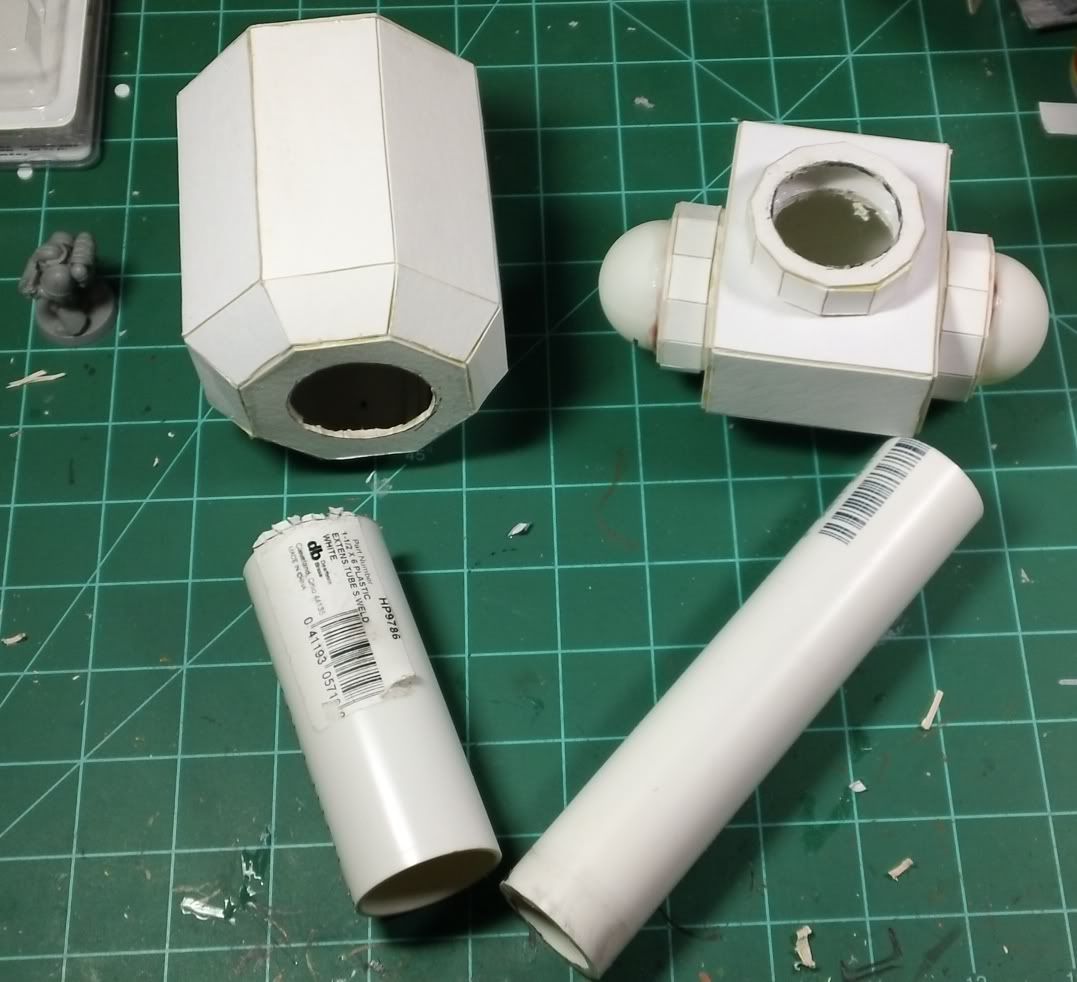
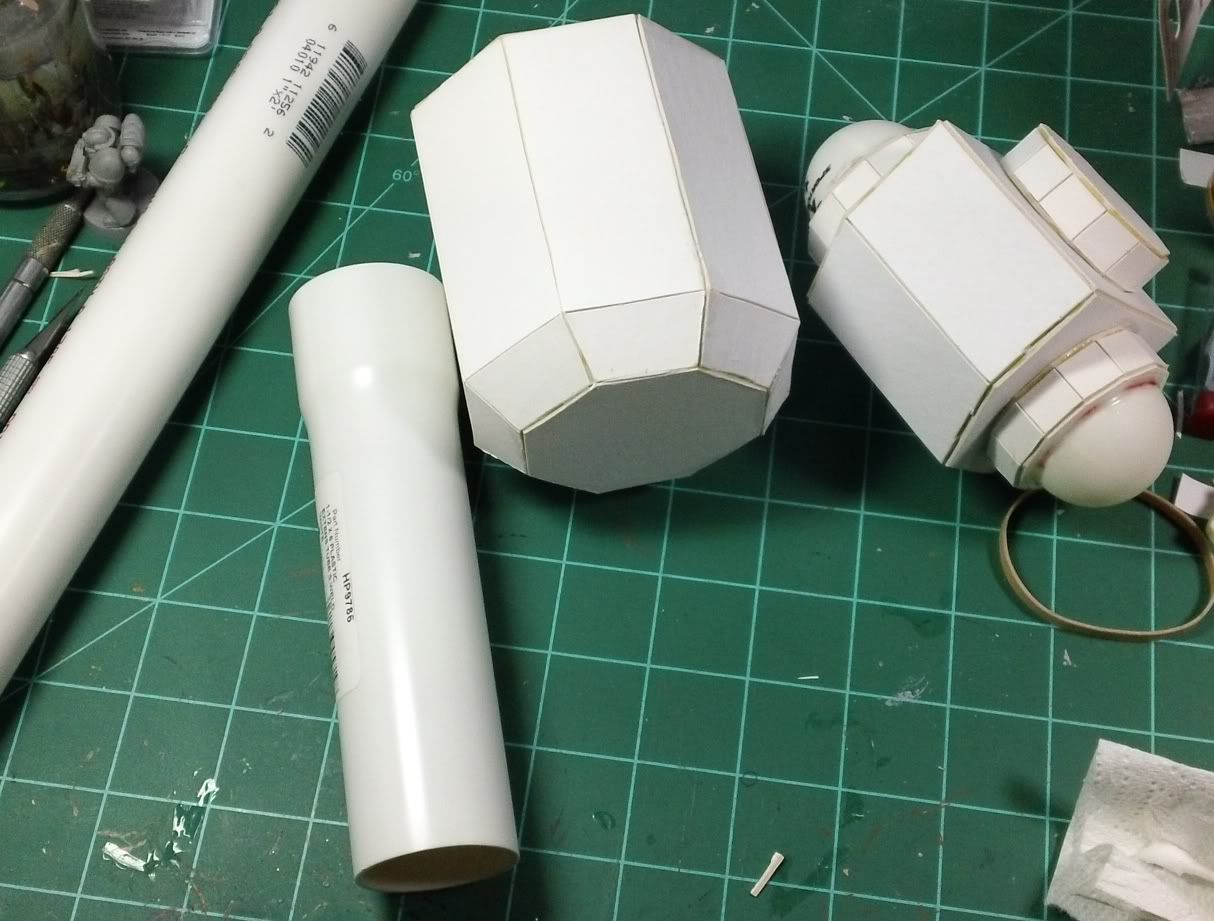
The items needed for this bit of the project were picked up at my local DIY store for about $3.50 US. They consist of a piece of pvc pipe and some sort of fitting I found that slips over it nicely. And of course the parts of the titan to be modified...


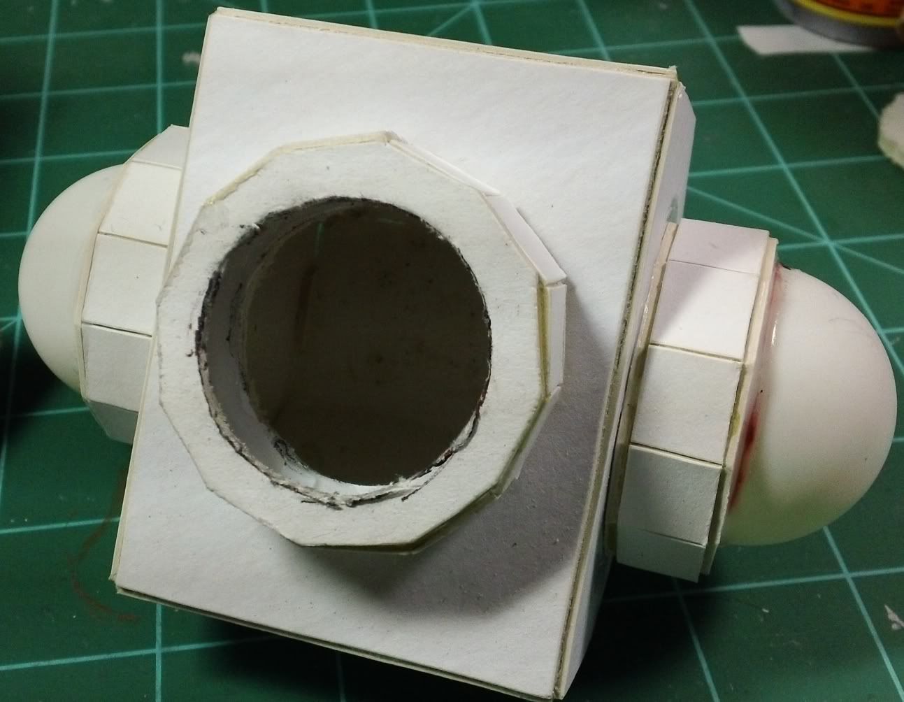
The first job was to carefully trace the holes that would need to be cut in the titan using the actual pvc pieces as a guide. Then of course, cutting those holes out. This one was a pain as it is two parts glued together, so three layers of matte board to go through...


Next I inserted the female part of this joint into it's titan piece and traced a line around where the cut needs to be for it to be flush. I've raised it up a bit so you can see the line in this pic...


Once that was cut, I placed the male part of the joint inside and traced around the edge where it needed to be cut off. I then subtracted just a bit for good measure and cut it to length. The results can be seen below...


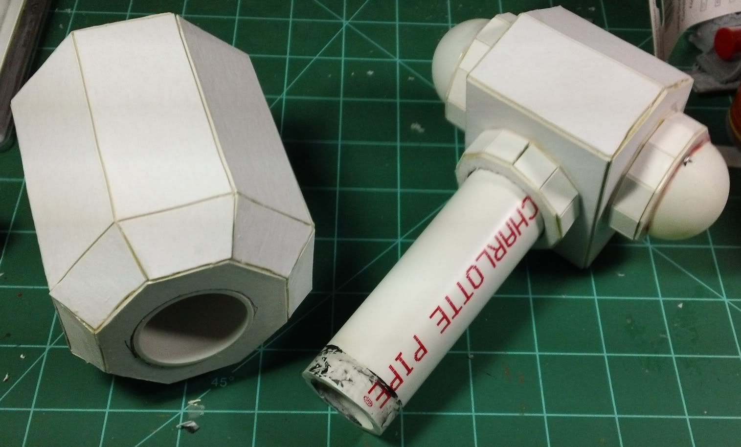
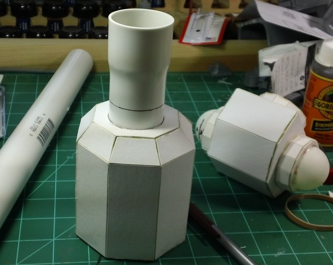
Being extra careful and using Gorilla Glue (hence the extra caution) I glued each piece into its respective titan part...


Then I realized I needed some way to keep the waist from spinning around, which would cause imbalance I theorize. To do this was a little extra work, but I think it was worth it in the end.

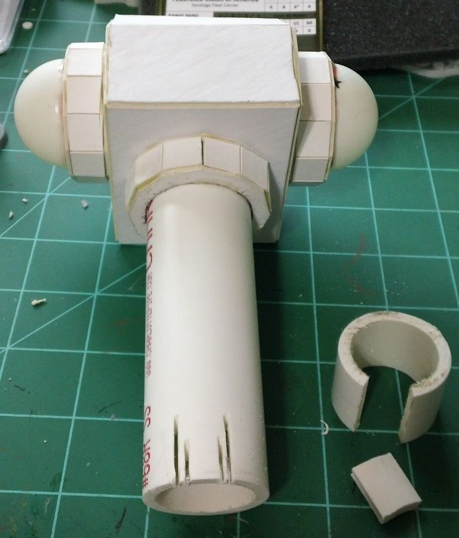
I got a spare piece of the pvc pipe I bought and cut a small section out of it...


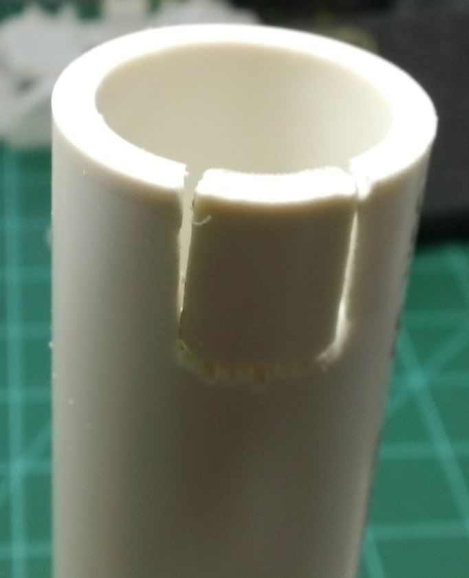
Then I cut a corresponding section out of the male part attached to the titan piece. You can see the beginning of this in the photo above. I cut vertical lines in the piece over and over until it was easy to snap the thin pieces off and clean it up with a hobby knife. This leaves a bit that will fit like this...


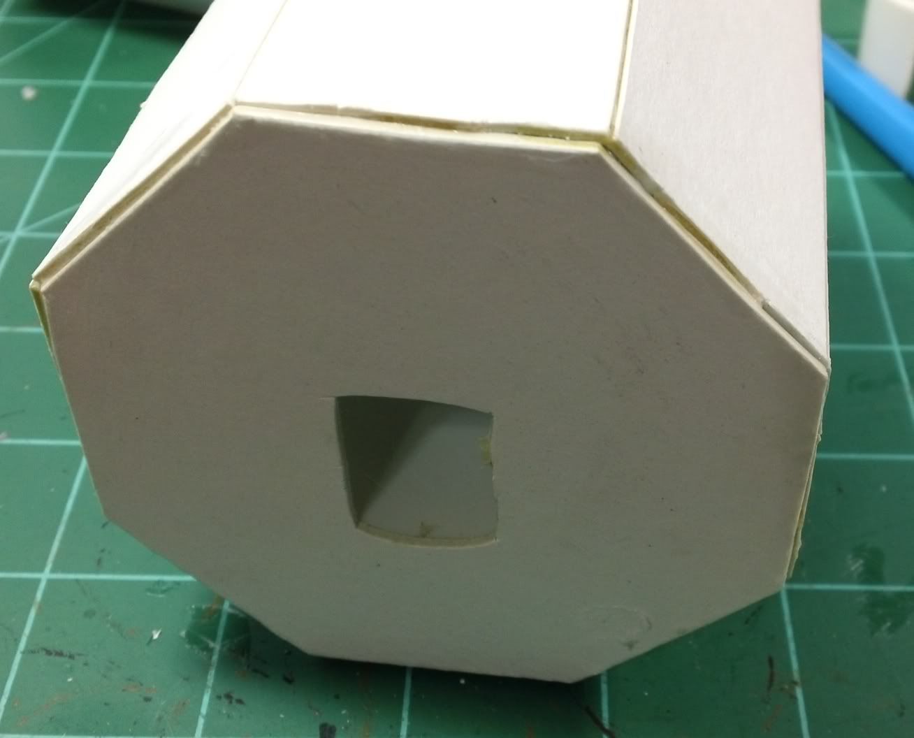
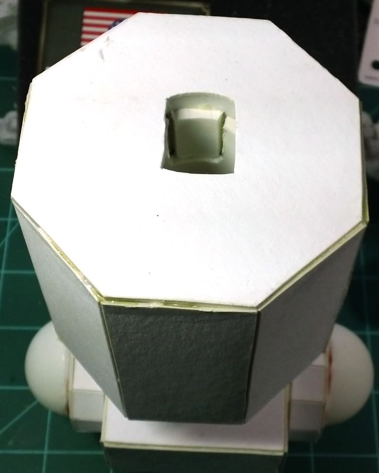
Next I cut an access hole in the top of the body. This will be covered by the Church part of the titan so no worries about the hole...


After roughing up the surfaces to be glued, I put the two titan parts in the position I wanted them to "lock" into. I glued the piece in place with Gorilla Glue using the access hole and a small clamp (sorry I didn't get a pic of that) to hold the piece while it dried. Resulting in a waist that no longer spins!


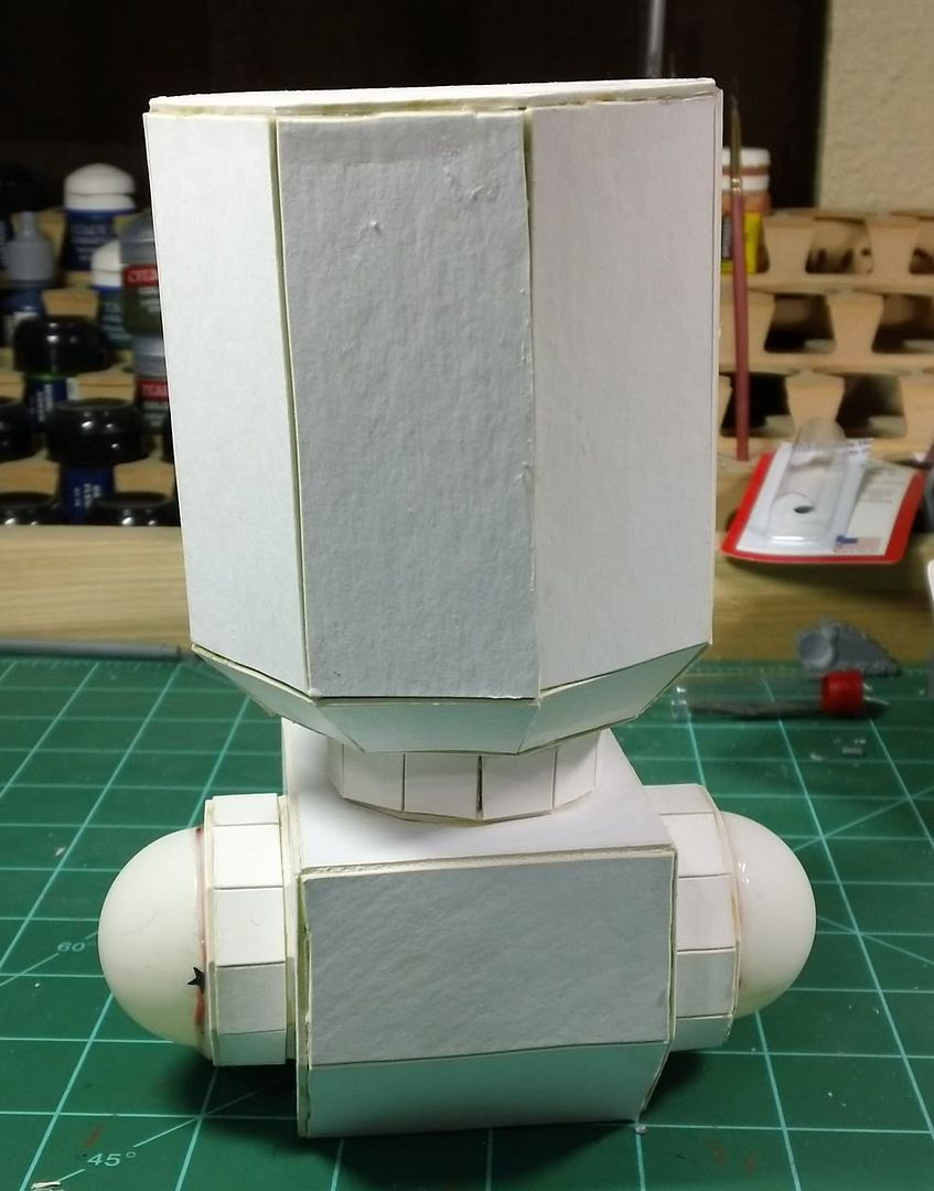
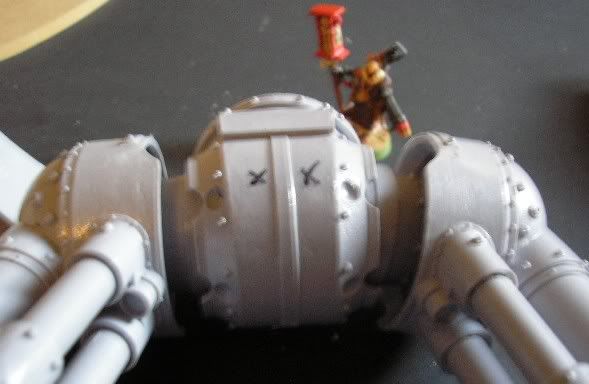
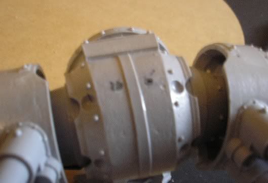
Here is a finished shot. It's straighter than it looks, but there is some sort of optical illusion going on in this pic...


Remember, this whole idea was sparked by a comment on my last blog. Your fellow bloggers can, and will, often think of things that you never considered. We are our best source of ideas for each other to tap.

Thanks for stopping by. Feel free to leave comments, criticisms, and witticisms in the comments area. Especially if you have any awesome ideas, I love to steal those!

Sunday, February 28, 2010

Super Glue Quick Tip

I was reading a post by Ron over at From The Warp about Pinning a BloodThirster. In his article, Ron uses green stuff as sort of a filler/adhesive along with super glue to pin some items. This works great on larger parts where you need a great deal of strength... though I usually two part expoxy anything needing a pin personally. It did remind me (in some odd round about way) of something I read somewhere (if someone can cite where I'll add the link later) about using paper towel material as a filler for a super glued joint.

The idea is that many times there is excess room in, for example, a ball and socket joint that makes the point of contact for the glue on the surfaces very low. When you put something in there to soak up the empty space, you get a more solid join. Here is how I do it.

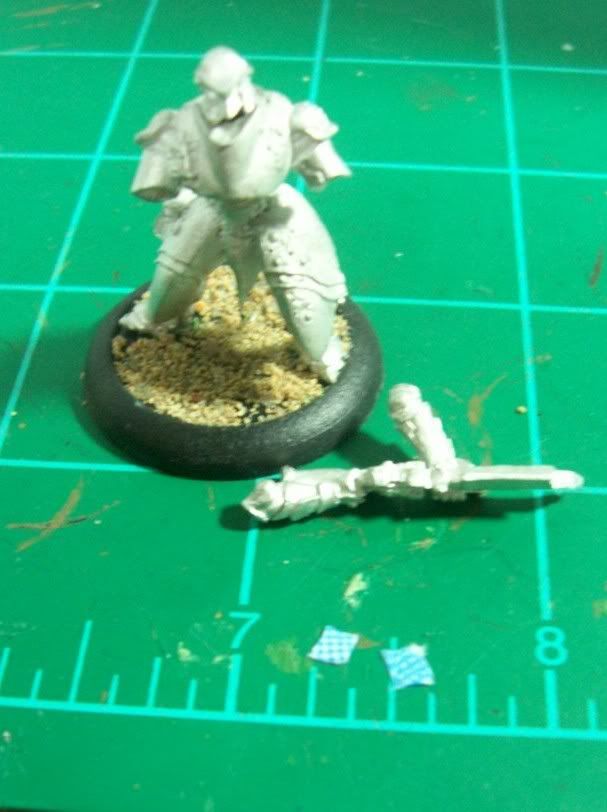
In the picture below you can see the Retribution Invictor is ready for his arms. The arms are ready and two tiny pieces of paper towel material are nearby. The paper towel was cut from a blue design to show up better in the pictures.


Next, I put a very tiny amount of super glue into the receiving side of the joint, in this case the main body of the mini. Then I use the tip of an exacto knife to pick up the tiny pieces of paper towel and place them into the joint. You don't want to put so much glue in there that they become soaked. Once soaked the paper towel hardens pretty darn quick and we want it to stay soft and pliable at this stage.


For the final step I put a generous amount of super glue on the remaining part to be joined, in this case the arms. When I place the arms in the sockets the paper towel will soak up the excess glue and conform to both halves of the join. So instead of arms that are glued on, but only touching in some areas of the join, I now have arms that are solidly glued to paper towel (which is hard as a rock now) and paper towel that is solidly glued to the rest of the mini.


I don't know how many people know this tip already, but if I help just one person prevent the arms of their tiny warriors from falling off, then I've done my job! As always, feel free to let me know what you think. I'm always keen to hear from you folks out on the inter-web!

Friday, January 29, 2010

Marauder Destroyer Pt. 2 (Landing Gear Magnets)

I've been working for a couple days on the landing gear for the Marauder Destroyer. Well, a day and half was thinking type work... better to over think it than under think it, right? My whole reason for even considering this is that I would like to have the option of a flying base with gear up or a static pose with gear down. With the ability to pose the plane with gear down it can double as scenery or even a largish objective marker when not in play.

I figured magnetizing the struts and such to the plane would be easy enough. The problem was magnetizing the flat pad at the bottom of the gear in a way so that it could attach to either the bottom of the struts, or the bottom of the plane with struts set aside. Then it occurred to me that the pads are only detailed on the upper side. When the gear is up you see only the flat bottom, easy to replicate with plastic card. More on this towards the end. First, here's how I got my landing gear struts and plane magnets to line up.

First I drilled a hole almost deep enough to set two magnets on top of each other into.


It is important that the top magnet is slightly out of the hole as can almost be seen here...


I placed a small drop (very small) of super glue on the top magnet surface and then held the gear strut assembly in place firmly.


This attaches the top magnet to the strut assembly in the just the perfect spot. Next I went back and drilled the hole a little deeper so that two magnets would sit in the hole without sticking out. They are quite flush with the planes surface. I placed a second magnet on the one that is now glued to the strut assembly. Put a little glue into the hole in the plane and used the magnet and strut to push the second magnet into the plane body. This assures that the magnets are polarized correctly, though if you're careful you could just as easily push the magnet into the plane with your finger or other non metallic tool.

Now with the strut assembly magnetized, I added a brass rod pin to help against twisting forces. There were two small rivets on the back side of the struts, I simply shaved one off and drilled through where it once was. Leaving the brass rod sticking up out of the whole replaces the rivet. The rod is larger than the diameter of the old rivet, but I think it looks fine. They might have used a larger rivet in order to make it more secure in 40k pretend land anyway!


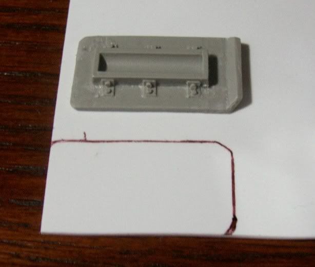
I mentioned earlier about the pads on the gear being fabricated. I just laid out an existing pad and traced around it to get the general shape. Then, cut it out and trimmed it to exact size. There is a slant at one end and this was added by scoring the plastic and bending it carefully.


The original...


And the copy...


(Since you never see the underside of the 'up' landing gear, it doesn't matter much how it looks!)

And a shot of the whole bunch happily magnetized together...


I know this was a lot of post for just a bunch of landing gear. I wanted to share the way I did it in hopes of inspiring others. Even if they're only inspired to tell me their favorite way to magnetize flat surfaces together!

Monday, April 6, 2009

Things Aren't Like They Used To Be...

And they probably never were. One of the wisest things I've ever been told.

You all have Ian over at Heroes Of Armageddon and his Blast From the Past blog to thank for this post. After reading his blog, digging up some GW fossils started to sound like fun.

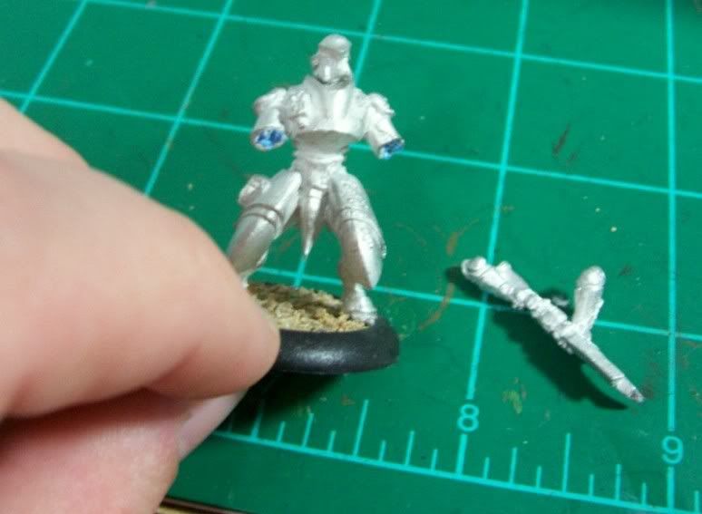
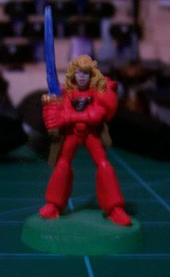
First off we have a rare old figure. The Female Adventurer In Power Armor. I will tell you that the head is from a Reaper miniature as the original was basically a blob with a bowl cut. There were two different minis made, this is one, the other I lost a million or so years ago.


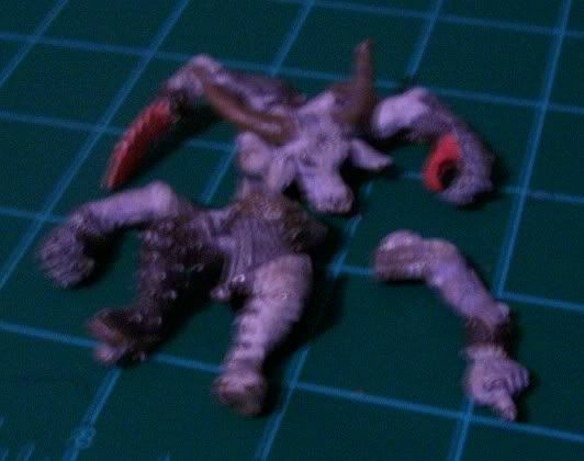
The next mini is one of my all time favorites. It's an original Keeper Of Secrets. It's been pulled apart as it has been my intention for the last couple years to redo this guy/gal/thing. I always liked the minotaur shape of these guys. It's more menacing than a scrawny hermaphrodite in my opinion.


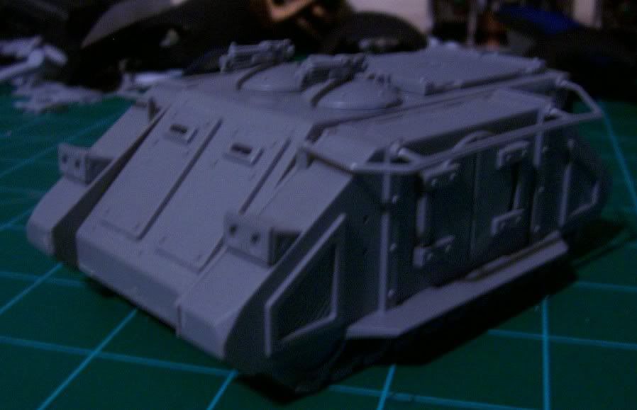
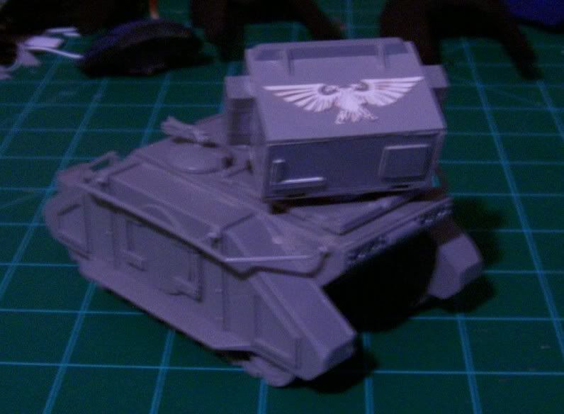
The next is a complicated piece. It would make an awesome tutorial, but it would be over ten years too late. It's an old style Rhino that can be transformed into a Whirlwind. You see, once upon a time, there was no model for the Whirlwind. Conversion was the only way to go. I've got two of these around and about. The other is in need of some repair though. Believe it or not, the only bits absolutely necessary that didn't come with the rhino are two fantasy shields, and a large square fantasy base.

Here it is a typical Rhino...

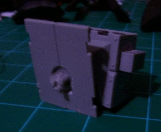
Inside extra bits can be stored. The openings on the opposite side (old rhinos were the same hull piece top and bottom) have been covered up with plastic card.

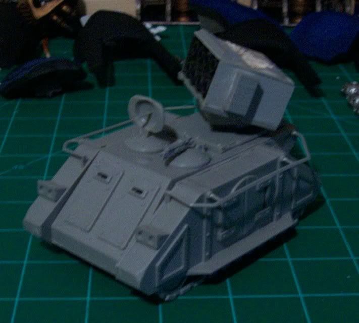
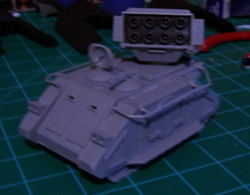
A Whirlwind launcher is fabricated from plastic card and bits. It's mounted on a set of rear doors with a pair of old Warhammer Fantasy shields and some scrap sprue to make it able to rotate.

Swap out the front hatches for a blank one and one with a home made radar dish (that also rotates), and you have a Whirlwind!

The Aquila on top of the launcher is carefully cut out from a Second Edition Wargear Card and glued on. Gives a nice three dimensional decoration. The missile rack itself is made from the bottom of an old square Fantasy base.

Note the little bumps inside each 'tube' on the launcher which are the missiles.


There is my trip down memory lane. I've more old stuff hidden all about, but it will wait for another day. Thanks for indulging me.

Friday, April 3, 2009

Reaver Titan Pt 15 (Warnings and Updates)

Just a quick update and words of warning/wisdom for any future Reaver builders out there...

While it's often advantageous to assemble things in a different order than the instructions show, be sure to test all variables first. When gluing the toes in place on the foot, I made extra sure that the large piston guards would be able to be put into place with the toe already on. What I did not test, probably due to it's smaller less important looking size, was the ability to place the smaller toe pistons into position with the toe already on. Because of the way the toe pistons (two per toe) go into the large piston guard, there is no way to do it without placing them as you slide the actual toe into position. So, I got to wrench, twist, wiggle, sweat, and pray in an attempt to get the toes back off the titan with minimal damage. Thank goodness they all came off without damaging the feet or legs!


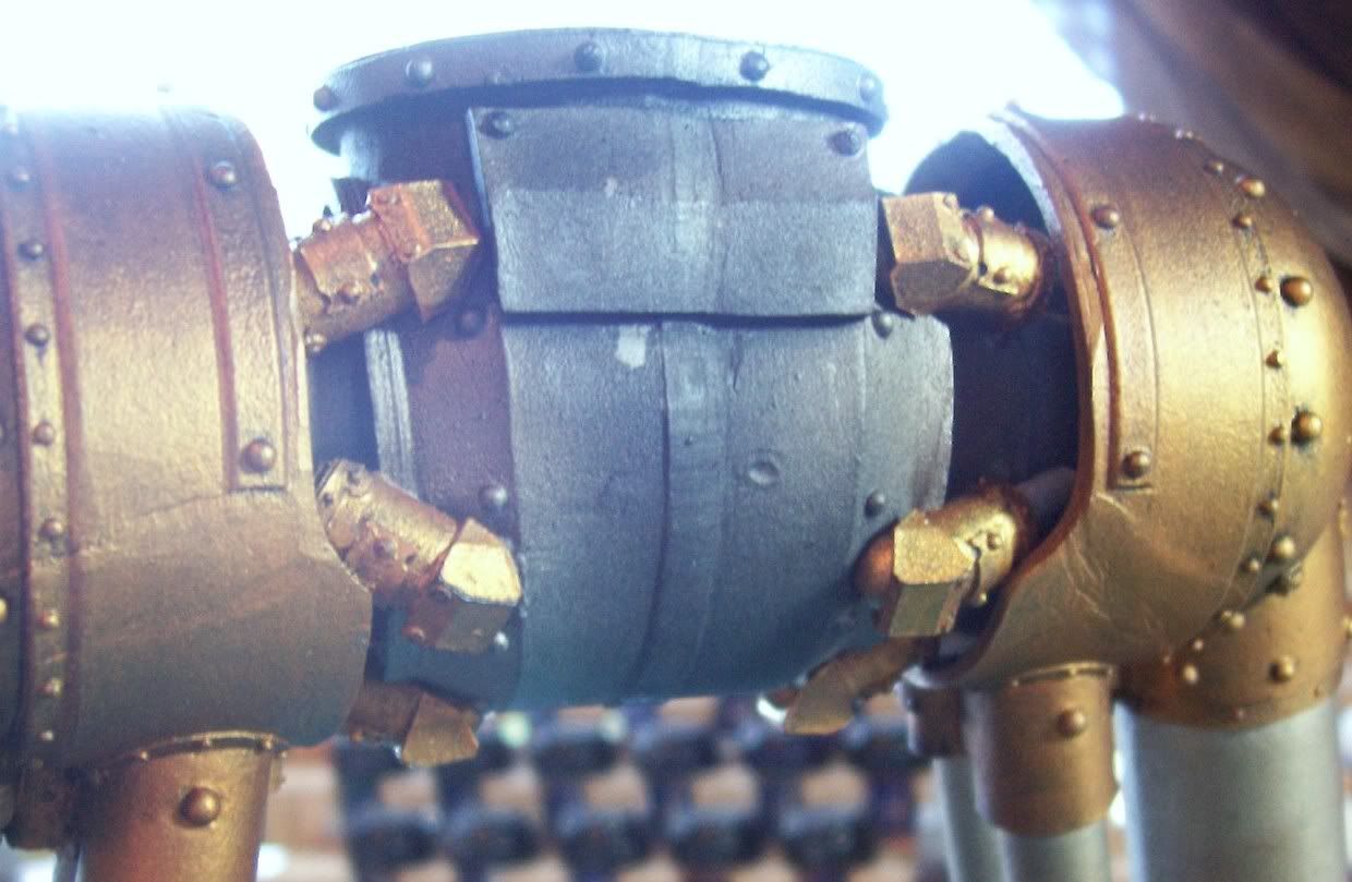
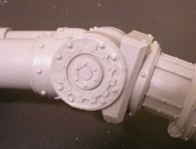
Another spot that can be troublesome, whether you follow the directions or not, are the pistons that actuate the hip joint. These simply don't fit well as the plating on the outer hip (the gold part) gets in the way. Here is a shot of some titan butt, or as I like to call it, "mechanicus porn".


On to better news!

The legs are starting to go together (now that the toes have come apart). The banners are in the works and we can all watch them come together over at From the Warp as Ron works his magic! And, I've finally found the right size drill bit and flush mounted some magnets to hang the banners from when they're finished...


It's Friday, things are moving along nicely with the Reaver so I'm not even going to suggest any kind of off the wall prose for comments. I will say that Klaus over at DEI GRECI mentioning his beergarden may just convince me to grab some beer and head out by the pool this evening! The wireless reaches out there so I can even check up on my fellow bloggers whilst I chill. That sounds nice... why do I even come in the house at all?

Wednesday, August 27, 2008

Reaver Titan Pt 5 (Legs Major Parts Assembly)

Well, it's been a few days and I'm happy to say the Reaver progress is coming along nicely. This blog will focus on the major (large parts) assembly. Without any further ado, let's go!

The first part is a no brainer. The titans thighs come in two large pieces. These I put together with one pin in the large piston of each leg. Not a lot of chance of weird stress angles or twisting, so I deemed one pin to be sufficient. For all these large pieces an old wire clothes hanger provides the pin material and a dremel tool and appropriate sized bit make the holes.


Next I moved my way down to the knee joint. The shape of the knee joint with all it's little ridges means that there is little chance of twisting, so once again a single pin does the job. A hole is drilled in the calf...


Then a hole for the thigh...


Then the two are joined. This is not so simple as it seems though. There was a lot of dry fitting to test and make sure that the knees were at an angle that would not interfere with later assembly. Once this angle was set (technically prior to drilling of course!) a pin is prepared and JB Kwik two part epoxy is mixed. I use a toothpick to slather the epoxy into the holes as much as possible, then on the pin itself as well. Hold the two leg parts together for a couple minutes and presto!


Next we move on to the feet, and a trick for making sure your pin-holes line up reasonably well. Just as in previous steps there is a lot of dry fitting to finalize the position I want. As a side note, whether I use the small individual foot bases I made, they have become invaluable in moving the feet around in once piece as I'm not ready to glue the toes yet. Now, to make sure that our pin-holes line up I use the following trick. Drill a hole in one of the two pieces like so...


Next, mix up some of your favorite sculpting putty. Here I've used Green Stuff. flatten a bit of the putty on the piece without a hole.
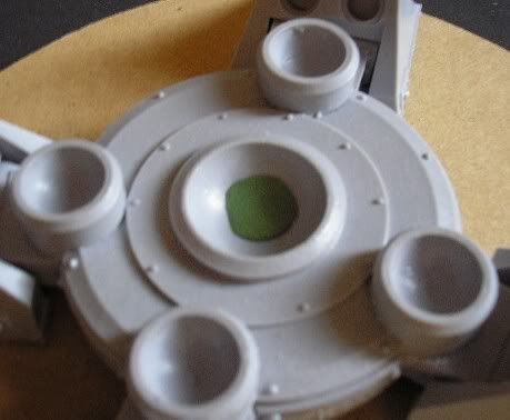


Lubricate the surface of the putty and place the piece with the hole down onto the piece with the putty being careful to press the two together in the same shape you want the final joint. Press hard. Pull them apart carefully and you will have a squished bit of putty... except where the original hole was! There you will find a little bump cast from the hole.
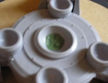


Stick your hobby knife through this bump and mark the spot. Now you know where to drill to get the receiving pin-hole where you want it.
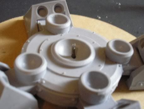


Now if you are like me, you will have a little bit of play in the fit of your pinned feet before gluing. This is a good thing. After preparing both feet and legs for attaching, I get the hips handy. I placed the epoxy in the holes and on the pin as mentioned above. I then place the legs down into the feet. To make sure the angle is right, I hold the two legs together at the tops of the thighs with the hips in place. The epoxy takes a few minutes to set, but it's time well spent just holding the legs in place.


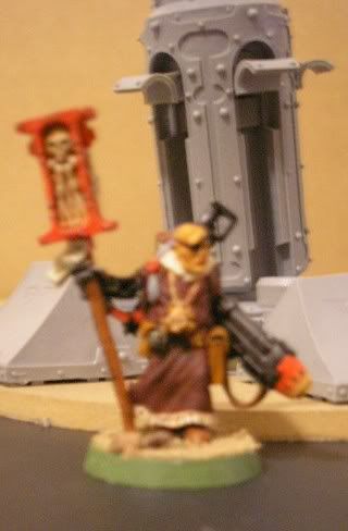
A priest jumped into this photo to show scale. I'm going to try to remember to place him around during pictures to show the scale of things.

The next step is to epoxy the hips together. This will involve no pins at this point... they will come though. I follow the same procedure of holding the legs in place with the hips as I did above, except this time it's the legs and hips being glued.

This works fine, but what about pins? This is a ball joint, a major ball joint which is susceptible to twisting stress in several directions! The answer is simple. Looking at the instructions I know there will be a cod piece and a butt piece in place that will cover the front and backs of the hips. So I mark a spot on each hip front and back and get ready to drill...


This area on the front and back are completely covered in a later step. Plus, the holes will line up because the pieces are already glued in place!


And after filling the holes with epoxy, placing the pins, and trimming the excess, we have very well pinned hips that are not likely to succumb to any twisting stress!


I used this same procedure to add another pin to the bottom of each foot. Once again, it will never be seen due to it's location and it's easy to do as the parts are already together.

This leaves us with the major assembly of the legs finished from Hips to Feet. Everything else is really just things that will be added on. The astute among you may have noticed that the upper thigh developed a ball joint to fit into the hip after the first step above. Those pics came out something awful but it is simply a circle shaped joint in the thigh. This was pinned with two pins as this is another joint that can move if only one pin was used in the center. Here is a picture of the final leg assembly as it sits on my workbench right now, as you can see the priest is still walking about blessing the feet (it's all he can reach)...
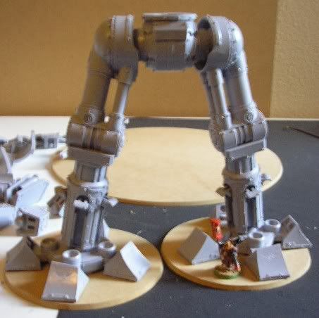


There is a little extra bend in the right leg. Not too dynamic, but better than just standing spread eagle I think. I'd like to thank you for joining me for another installment on what looks to become a 1000 part blog project. I know this was a long one, I'll try to make smaller more frequent posts in the future... this one just got away from me! And, as usual, leave me your comments, questions, criticisms, hopes, dreams, anecdotes, or whatever you've got. I have to get some use out of that fancy new comments program!
Monday, August 25, 2008

Reaver Titan Pt 4 (Legs and Bases)

Welcome back! Today is kind of a hodge-podge of an update. A little of a couple different things going on. Let's go have a look...
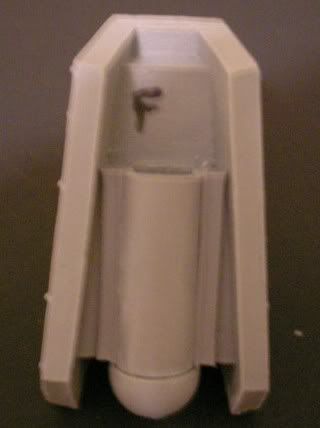
First off is another tip. I ran across a situation and had to use my trusty sharpie marker to bail me out again. There are some resin pieces that have a part number or other designation on them. Such as this one (note the "F" cast in the center).


There is a half cylinder bit that will cover this letter up, forever hiding the important information that is cast in the piece. So, before gluing that piece on I used the marker to replicate the information. So now even with the extra piece glued on, we can tell this part is "F", or 'front'.


Another bit of advice I have is on gluing parts together. As this project goes on I will be using a lot of epoxy. Sure, for small stuff I'll still use the Super Glue. But, for larger pieces I'll be using an epoxy called JB Quick. I love this stuff. It takes about four minutes to cure to the point that the piece is totally secure, but that gives you some working time. It also has another great feature... From about four minutes till around twenty minutes the consistency of the epoxy is such that if you have allowed some to squish out of the joint, you can carve it away with an exacto knife and it will fill any crevice automatically! Here are a couple shots of epoxy in action...


This is a shot of the first piece to get the epoxy treatment. It is an interior view of the leg armor. The bits you glue on the armor to (later) mount it on the legs are a pain. You have to apply glue then hold the piece onto the leg to ensure that the pieces are in the right position. Super Glue drys too fast, so the four minute work time is perfect here. Plus the resulting join will be stronger than the super glue could have ever hoped to be!


As you can see, some small parts are being glued already. These are all minor pieces that are required to go onto the major parts before actual assembly. I've spared you the tedium of explaining every single tiny bit that's glued on. I assure you though, that I will be sharing all the major assembly and any smaller bits that warrant special attention or are just plain cool!

Finally we move on to the dilemma of the base. I've narrowed it down to a couple of options. These are based (ha ha 3d6 pun damage to all readers) on several factors. Playability; how will it work on a game board, will it even fit? Functionality; will it hold the titan up and add at least some stability? I've decided that the pose will be fairly static. I will probably bend one knee a bit, but this thing won't be dancing a jig anytime soon. With this in mind, I bought some MDF board and did some cutting on the band saw and some sanding to bevel the edge. Thanks to my wonderful Dad for having these kind of tools laying around in his garage, even if he does live across town!

This first shot is a two base idea. One for each foot. Minimal 'foot print' (wow I'm punny indeed) but still adding some stability and preventing too much pressure ever being put on one or two toes are the main advantages here...


Then there is the full base option. This adds maximum stability at the cost of being freaking huge. The item at the bottom of the pick is a standard 12" (30cm) ruler. Also worth noting; this is a 14" diameter base, I also made a 16" in case this one doesn't allow enough leg room.


You may notice that I left the feet on the smaller 6" diameter bases in this last shot. A third idea I've had is to use both methods. I could mount the feet on the smaller individual bases, then use powerful magnets to affix those to the larger base.

I'm hoping to get to the big stuff, drilling and pinning large parts, in the next few days. So keep an eye out for another post when that's underway.

Any comments, questions, or better yet suggestions are appreciated. You can even toss in a pun if that's how you roll.
Related Posts with Thumbnails